This publication discusses the basic terms, laws and methods for calculating the EMF of magnetic induction. With the help of the materials presented below, you can independently determine the current strength in interconnected circuits, the voltage change in typical transformers. This information is useful for solving various electrical problems.
Magnetic flux
It is known that passing current through a conductor is accompanied by the formation of an electro magnetic field... The work of speakers, locking devices, relay drives, and other devices is based on this principle. By changing the parameters of the power source, the necessary force forces are obtained to move (hold) the aligned parts with ferromagnetic properties.
However, the opposite is also true. If, between the poles of a permanent magnet, move a frame made of a conductive material along a corresponding closed circuit, the movement of charged particles will begin. By connecting the appropriate devices, you can register the change in current (voltage). In the course of an elementary experiment, you can find out the increase in the effect in the following situations:
- perpendicular arrangement of the conductor / lines of force;
- acceleration of movements.
The picture above shows how to determine the direction of current in a conductor using a simple rule.
What is EMF of induction
The movement of charges noted above creates a potential difference if the circuit is open. The presented formula shows exactly how the EMF will depend on the main parameters:
- vector expression of magnetic flux (B);
- length (l) and movement speed (v) of the control conductor;
- angle (α) between motion / induction vectors.
A similar result can be obtained if the system is composed of a stationary conducting circuit, which is acted upon by a moving magnetic field. Having closed the loop, suitable conditions are created for the movement of charges. If you use many conductors (coil) or move faster, the amperage will increase. The presented principles are successfully applied to transform mechanical forces into electrical energy.

Designation and units
The EMF in the formulas is denoted by the vector E. This means the tension that is created by external forces. Accordingly, this value can be estimated from the potential difference. According to current international standards (SI), the unit of measurement is one volt. Large and small values are indicated using multiple prefixes: "micro", "kilo", etc.
Faraday's and Lenz's laws
If electromagnetic induction is considered, the formulas of these scientists help to clarify the mutual influence of significant system parameters. Faraday's definition makes it possible to clarify the dependence of the EMF (E- average value) from changes in magnetic flux (ΔF) and time (Δt):
E = - ΔF / Δt.
Intermediate conclusions:
- the current increases if per unit time the conductor crosses a greater number of magnetic field lines;
- "-" in the formula helps to take into account the mutual relations between the polarity E, the speed of the frame movement, the directionality of the induction vector.
Lenz substantiated the dependence of the EMF on any changes in the magnetic flux. When the coil loop is closed, conditions are created for the movement of charges. In this case, the design is converted into a typical solenoid. A corresponding electromagnetic field is formed next to it.
This scientist substantiated an important feature of the induction EMF. The field formed by the coil prevents the external flow from changing.
The movement of a wire in a magnetic field
As shown in the first formula (E = B * l * v * sinα), the amplitude of the electromotive force largely depends on the parameters of the conductor. More precisely, the influence is exerted by the number of lines of force per unit length of the working area of the circuit. A similar conclusion can be made taking into account the change in the speed of movement. One should not forget about the relative position of the marked vector quantities (sinα).
Important! Moving the conductor along the lines of force does not provoke the induction of an electromotive force.
Spinning coil
Optimal placement of functional components while moving at the same time is difficult using the straight wire shown in the example. However, by bending the frame, you can get the simplest generator of electricity. The maximum effect is provided by an increase in the number of conductors per unit of working volume. The design corresponding to the noted parameters is a coil, a typical element of a modern alternator.
To estimate the magnetic flux (F) you can apply the formula:
F = B * S * cosα,
where S is the area of the considered working surface.

Explanation. With uniform rotation of the rotor, a corresponding cyclical sinusoidal change in the magnetic flux occurs. The amplitude of the output signal changes in the same way. It is clear from the figure that the gap between the main functional components of the structure has a certain value.
EMF of self-induction
If an alternating current is passed through the coil, an electromagnetic field with similar (uniformly changing) power characteristics will be formed nearby. It creates an alternating sinusoidal magnetic flux, which, in turn, provokes the movement of charges and the formation of an electromotive force. This process is called self-induction.
Taking into account the considered basic principles, it is easy to determine that F = L * l. The L value (in henry) determines the inductive characteristics of the coil. This parameter depends on the number of turns per unit length (l) and the cross-sectional area of the conductor.
Mutual induction
If you assemble a module from two coils, under certain conditions, the phenomenon of mutual induction can be observed. An elementary measurement will show that as the distance between the elements increases, the magnetic flux decreases. The opposite is observed as the gap decreases.
To find suitable components when creating electrical circuits, it is necessary to study thematic calculations:
- you can take, for example, coils with a different number of turns (n1 and n2);
- mutual induction (M2) when passing through the first current loopI1 will be calculated as follows:
M2 = (n2 * F) / I1
- after transforming this expression, the value of the magnetic flux is determined:
F = (M2 / n2) * I1
- to calculate the emf of electromagnetic induction, the formula will fit from the description of the basic principles:
E2 = - n2 * ΔF / Δt = M 2 * ΔI1 / Δt
If necessary, you can find the ratio for the first coil using a similar algorithm:
E1 = - n1 * ΔF / Δt = M 1 * ΔI2 / Δt.
It should be noted that in this case the force (I2) in the second working circuit matters.
The joint influence (mutual induction - M) is calculated by the formula:
M = K * √ (L1 * l2).
A special factor (K) takes into account the actual strength of the connection between the coils.
Where are different types of EMF used
Moving a conductor in a magnetic field is used to generate electricity. The rotor rotation is provided due to the difference in liquid levels (HPP), wind energy, tides, fuel engines.
![]()
A different number of turns (mutual induction) is used to change the voltage in the secondary winding of the transformer as needed. In such designs, the mutual coupling is increased by using a ferromagnetic core. Magnetic induction is used to generate a powerful repulsive force when creating ultramodern transport routes. The created levitation makes it possible to eliminate the friction force and significantly increase the speed of the train.
Video
- Electric current, current density, electric voltage, energy when current flows, power of electric current
- Electricity
Electric current is a phenomenon of the ordered movement of electric charges. The direction of movement of positive charges is taken as the direction of the electric current.Electric current formula:

Electric current is measured in amperes. SI: A.
Electric current is indicated by Latin letters i or I... Symbol i (t) denotes the "instantaneous" value of the current, i. e. an arbitrary current at any time. In a particular case, it can be constant or variable.
Uppercase latin letter I denoted, as a rule, a constant current value.
In any section of an unbranched electrical circuit, a current of the same magnitude flows, which is directly proportional to the voltage at the ends of the section and is inversely proportional to its resistance. The magnitude of the current is determined by Ohm's law:
1) for DC circuit
2) for an alternating current circuit,
where U- voltage, V;
R- ohmic resistance, Ohm;
Z- total resistance, Ohm.
Ohmic resistance of the conductor:
,
where l- conductor length, m;
s- cross section, mm 2;
ρ - resistivity, (Ohm mm 2) / m.
Dependence of ohmic resistance on temperature:
R t = R 20,
where R 20- resistance at 20 ° C, Ohm;
R t- resistance at t ° C, Ohm;
α - temperature coefficient of resistance.
AC circuit impedance: ,
,
where is the active resistance, Ohm;
- inductive resistance, Ohm;
- inductance, Mr.; - capacitive resistance, Ohm;
- capacity, F.
Active resistance is greater than ohmic resistance R:
,
where is the coefficient taking into account the increase in resistance at alternating current, depending on: the frequency of the current; magnetic properties, conductivity and conductor diameter.
At power frequency, for non-steel conductors, take and count. - Current density
Current density ( j) Is the current strength calculated per unit cross-sectional area ( s)
.
For a uniform distribution of the current density and its co-directionality with the normal to the surface through which the current flows, the current density formula takes the form:
,
where I- current through the cross-section of a conductor with an area s.
SI: A / m 2 - Electrical voltage
With the flow of current, as with any movement of charges, the process of energy conversion takes place. Electrical voltage - the amount of energy that needs to be spent on moving a unit of charge from one point to another.
Electric voltage formula:
The electrical voltage is indicated by a Latin letter u... Symbol u (t) denotes the "instantaneous" voltage value, and the capital Latin letter U as a rule, constant voltage is indicated.
Electrical voltage is measured in volts. SI: V. - Energy with the flow of electric current
Energy formula, with the flow of electric current:
SI: J - Power when electric current flows
Power formula, with the flow of electric current:
SI: W.
- Electrical circuit
- Electrical circuit Is a set of devices designed for the flow of electric current through them.
These devices are called circuit elements. - Sources of electrical energy- devices that convert various types of energy, such as mechanical or chemical, into electrical energy.
- Ideal voltage source- a source, the voltage at the terminals of which does not depend on the magnitude of the current flowing through it.

The internal resistance of an ideal voltage source can be conventionally taken equal to zero. - Ideal current source- a source, the amount of current flowing through which does not depend on the voltage at its terminals.

The internal resistance of such a source can be conventionally taken equal to infinity. - Receiver Is a device that consumes energy or converts electrical energy into other forms of energy.
- Bipolar Is a circuit that has two terminals for connection (poles).
- Ideal R-element (resistive element, resistor)- this is such a passive element of the circuit, in which an irreversible process of converting electrical energy into thermal energy takes place.
The main parameter of a resistor is its resistance.
Resistance is measured in ohms. SI: Ohm
Conductivity Is the reciprocal of resistance.
.
The conductivity is measured in siemens. SI: Cm.
R-element power formula: .
.
R-element energy formula: .
. - Ideal C-element (capacitive element, or capacitor)- this is such a passive element of the circuit, in which the process of converting the energy of an electric current into energy takes place electric field and vice versa. There is no energy loss in an ideal C-cell.
Capacity formula:
... Examples:,.
Tank current:
Tank voltages: .
.
Commutation law for a capacitive element. At a current of finite amplitude, the charge on the C-element cannot change abruptly: .
. .
.
With a constant capacitance, the voltage across the capacitive element cannot change abruptly: .
.
C-element power:.
At p> 0- energy is stored when p< 0
C-element energy: , or
, or  .
.
Capacitance is measured in farads. SI: F. - Ideal L-element (inductive element or inductor)- this is such a passive element of value, in which the process of converting the energy of an electric current into the energy of a magnetic field and vice versa takes place. There is no energy loss in an ideal L-cell.
For a linear L-element, the inductance formula ( L) has the form:
,
where is the flux linkage.
Inductance is denoted by a letter and plays the role of a coefficient of proportionality between flux and current.
Inductive element voltage:
.
Inductive element current: .
.
Commutation law for an inductive element. At a voltage of finite amplitude, the flux linkage cannot change abruptly: .
. .
.
With a constant inductance, the current in the inductive element cannot change abruptly: .
.
L-element power:.
At p> 0- energy is stored when p< 0 - energy is returned to the source.
L-element energy:, or .
If by the moment of time, the energy is equal to 0, then
Inductance is measured in henry. SI: Mr.
Example:. - R, L, C- the main passive two-pole elements of electrical circuits.

- Basic laws of electrical circuits
- Ohm's law for a section of a circuit that does not contain an EMF source.
Ohm's law for a section of a circuit that does not contain an EMF source establishes a relationship between current and voltage in this section.
With regard to this figure, the mathematical expression of Ohm's law is: , or
, or 
This equality is formulated as follows: with a constant resistance of the conductor, the voltage across it is proportional to the current in the conductor. - Ohm's law for a section of a circuit containing an EMF source
For the scheme
 .
.
For the scheme
 .
.
In general .
. - Joule-Lenz law... Energy released on resistance R when current flows through it I, proportional to the product of the square of the current strength and the resistance value:

- Kirchhoff's laws.
Topology (structure) of the circuit.
Electrical diagram- a graphic representation of an electrical circuit.
Branch- a chain section containing one or more series-connected elements and enclosed between two nodes.
Knot- the point of the chain where at least three branches converge. The nodes are numbered arbitrarily, usually in Arabic numerals. On the diagram, a node may or may not be indicated by a dot. As a rule, they do not indicate those nodes, the location of which is obvious (T-joints). If the intersecting branches form a knot, then it is indicated by a dot. If there is no point at the intersection of the branches, then there is no node (the wires lie on top of each other).
Circuit- a closed path that runs along several branches. Contours are independent if they differ by at least one branch. The contour is indicated by an arrow with the indicated direction of the bypass and a Roman numeral. The direction of the traversal is chosen arbitrarily. There can be many independent contours in the circuit, and not all of these contours are necessary to compose a sufficient number of equations to solve the problem.
1) the algebraic sum of currents flowing to any node of the circuit is equal to zero:
;
2) the sum of the currents flowing to any node is equal to the sum of the currents flowing from the node: . .
. .
Kirchhoff's second law:
1) the algebraic sum of voltage drops in any closed loop is equal to the algebraic sum of EMF along the same loop:
2) the algebraic sum of voltages (not voltage drops!) Along any closed loop is equal to zero:
. . - Matrix notation of Kirchhoff equations:
 ,
,
where A, V- coefficients at currents and voltages of the order p x p (p- the number of branches of the circuit; q- the number of circuit nodes);
I, E- unknown currents and given EMF
Matrix elements A are the coefficients for currents on the left side of the equations, compiled according to the first and second laws of Kirchhoff. The first rows of the matrix A contain the coefficients for currents in the equations drawn up according to the first Kirchhoff's law, and have elements +1, -1, 0, depending on the sign with which this current enters the equation.
Elements of the next rows of the matrix A are equal to the resistance values at the corresponding currents in the equations drawn up according to the second Kirchhoff's law, with the corresponding sign. Matrix elements V are equal to the coefficients for the EMF on the right side of the equations, compiled according to Kirchhoff's laws. The first rows of the matrix have zero elements, since the EMF on the right side of the equations written according to the first Kirchhoff's law is absent. The rest of the lines contain elements +1, -1, depending on the sign with which the EMF enters the equation, and 0 if the EMF is not included in the equation.
General solution of equations, compiled according to Kirchhoff's laws: ,
,
where - matrix of conductivity.
  .
.
Currents in each branch:
;
;
. - Rated operating mode of an electrical circuit element- this is the mode in which it operates with nominal parameters.
- Agreed mode- this is the mode in which the power supplied by the source or consumed by the receiver is at its maximum value. This value is obtained with a certain ratio (coordination) of the parameters of the electrical circuit.
- Idle mode- this is a mode in which there is no flow through the source or receiver electricity... In this case, the source does not give up energy to the external part of the circuit, and the receiver does not consume it. For the engine, this will be a mode without mechanical load in bulk.
- Short circuit mode- this is a mode that occurs when the opposite terminals of a source or passive element are connected to each other, as well as an energized section of an electrical circuit.
- If the current is constant, then there is no self-induction phenomenon and the voltage across the inductor is zero:
 , because
 - Direct current does not pass through the capacitor.
- Is a single source circuit with serial, parallel or mixed connection of receivers.

When daisy chaining the receivers:
I × R eq;
R eq = ΣR i.
When the receivers are connected in parallel, the voltage at all receivers is the same.
According to Ohm's law, the currents in each branch: .
.
According to the first Kirchhoff's law, the total current is:
E × G equiv;
G eq = G 1 + G 2 + ... + G n; R eq = 1 / G eq.
With a mixed connection:
R eq = .
. - Loop current method.
The method is based on the application of the second Kirchhoff's law and makes it possible to reduce the number of equations to be solved when calculating complex systems.
In mutually independent circuits, where for each circuit at least one branch enters only this circuit, conditional contour currents are considered in all branches of the circuit.
Loop currents, in contrast to branch currents, have the following indices: or
or 
The equations are made according to the second Kirchhoff's law for loop currents.
The branch currents are expressed in terms of the loop currents according to the first Kirchhoff's law.
The number of selected contours and the number of equations to be solved is equal to the number of equations compiled according to the second Kirchhoff's law:.
The sum of the resistances of all resistive elements of each circuit with a plus sign is the coefficient at the circuit current, has the following indices: or
or 
The sign of the coefficient for the current of adjacent circuits depends on the coincidence or non-coincidence of the direction of adjacent circuit currents. EMF are included in the equation with a plus sign if the directions of the EMF and the direction of the circuit current coincide. ... - Nodal Potential Method.
The method is based on the application of the first Kirchhoff's law and allows you to reduce the number of equations to be solved when finding unknown currents to. When drawing up equations, the potential of one of the circuit nodes is taken to be zero, and the branch currents are expressed through the unknown potentials of the remaining circuit nodes, and equations are written for them according to the first Kirchhoff's law. The solution of the system of equations allows one to determine the unknown potentials, and through them to find the currents of the branches.
With http: = "" title = "(! LANG: U_ (12) = (sum (i = 1) (m) (E_i / R_i)) / (sum (i = 1) (n) (1 / R_i) ) = (sum (i = 1) (m) (E_i * G_i)) / (sum (i = 1) (n) (G_i))">.!}
. - Proportional greatness method.
The method is used to find unknown currents in chain connection of resistive elements in electrical circuits with one source. Currents and voltages, as well as the known EMF of the circuit, are expressed through the current of the branch farthest from the source. The problem is reduced to solving one equation with one unknown. - Power balance
Based on the law of conservation of energy, the power developed by sources of electrical energy should be equal to the power of conversion in the circuit of electrical energy into other types of energy: .
.
- the sum of the capacities developed by the sources;
- the sum of the capacities of all receivers and irreversible transformations of energy within the sources.
The balance of capacities is made up to check the correctness of the solution found. In this case, the power introduced into the circuit by the energy sources is compared with the power consumed by the consumers.
Power formula for one resistor:
Total power of consumers:
P P=
Source power:
P source = P E + P J,
where P E = ± EI- the power of the EMF source (determined by multiplying its EMF by the current flowing in this branch. The current is taken with the sign obtained as a result of the calculation. A minus in front of the product is put if the direction of the current and the EMF do not coincide on the diagram);
P J = JU J- the power of the current source (determined by multiplying the source current by the voltage drop across it).
To determine U J, any circuit is selected that would include a current source. Denote a fall U J on the diagram against the source current, and write the contour equation. All quantities except U J, in this equation are already known, which allows you to calculate the voltage drop U J.
Power comparison: P source = P P... If the equality is met, then the balance has come together and the calculation of the currents is correct. - Algorithm for calculating a chain according to Kirchhoff's laws
- We arbitrarily put numbers and directions of unknown currents on the diagram.
- We arbitrarily put the numbers of nodes on the scheme.
- We compose nodal equations for arbitrarily chosen nodes (according to the first law).
- We mark the contours on the diagram and select the directions of their bypass.
- The number of designated contours is equal to the number of equations compiled according to the second Kirchhoff's law. In this case, none of the circuits should include a branch with a current source.
- We compose contour equations for the selected contours (according to the second law).
- We combine the equations in a system. We transfer the known values to the right side of the equations. We introduce the coefficients at the sought currents into the matrix A(left-hand sides of the equations) (we read about matrices). Filling in the matrix F by entering the right-hand sides of the equations into it.
- We solve the resulting system of equations ().
- We check the correctness of the decision by drawing up the power balance.
Example:.
- Sinusoidal current circuit- this is an electrical circuit in which the EMF, voltages and currents, changing according to a sinusoidal law:
- Alternating current Is a current that periodically changes in magnitude and direction and is characterized by amplitude, period, frequency and phase.
- AC Amplitude- it greatest value, positive or negative, taken by alternating current.
- Period- this is the time during which there is a complete oscillation of the current in the conductor.
- Frequency Is the reciprocal of the period.
- Phase Is the angle or, standing under the sine sign. The phase characterizes the state of the alternating current over time. At t= 0 phase is called initial.
- Periodic mode:
 ... The sinusoidal mode can also be referred to this mode:
,
where is the amplitude;
- initial phase; - angular speed of rotation of the generator rotor.
At f= 50 Hz glad / s.
 - Sinusoidal current Is a current that changes in time according to a sinusoidal law:
. - Average value of sinusoidal current (EMF, voltage), formula:
 ,
,
that is, the average value of the sinusoidal current is from the amplitude. Likewise, .
. - RMS value of sinusoidal current (EMF, voltage), formula:
... Likewise, .
. - The amount of heat released in one period by a sinusoidal current, the formula:
 .
.
RMS value of sinusoidal current I numerically equal to the value of such a constant current, which, in a time equal to the period of the sinusoidal current, emits the same amount of heat as the sinusoidal current. =R × I post 2 × T or I post=I=
 - Sinusoidal current crest factor (κ a) is the ratio of the amplitude of the sinusoidal current to the effective value of the sinusoidal current:
 .
. - Sinusoidal current waveform factor (κ f) Is the ratio of the effective value of the sinusoidal current to the average value of the sinusoidal current over the half period:
κ f= .
.
For non-sinusoidal periodic currents κ a≠, κ f≠ 1.11. This deviation indirectly indicates how much the non-sinusoidal current differs from the sinusoidal one. - any complex number can be represented:
a) in algebraic form
b) in trigonometric form
c) in exemplary form
rde - Euler's formula;
d) a vector on the complex plane,
where is the imaginary unit; - the real part of the complex number (the projection of the vector onto the real axis);
  - the imaginary part of a complex number (the projection of the vector onto the imaginary axis);
  - module of a complex number;
  - the main value of the complex number argument.
Solved examples on actions on complex numbers. - Sinusoidal current i
 .
. - Complex current amplitude- the complex number, the modulus and argument of which, respectively, are equal to the amplitude and the initial phase of the sinusoidal current:
. - Complex current (complex effective current):

- Sinusoidal voltage u can be assigned a complex number
 .
. - Complex voltage amplitude- the complex number, the modulus and the argument of which, respectively, are equal to the amplitude and the initial phase of the sinusoidal voltage:
. - Complex resistance:

Resistance in complex form expressed as a real positive number.
Complex reactance is expressed by imaginary numbers, and the inductive reactance ( X L) is positive, and the capacitive ( X C) is negative.
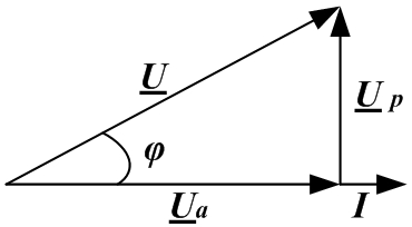
Impedance of a section of a circuit with serial connection R and X expressed as a complex number, the real part is equal to the active resistance, and the imaginary part is the reactance of this section. - Resistance triangle:


- Stress triangle:


- Capacity triangle:

Full power:
Active power:
Reactive power:
- Ohm's law in complex form:
. - The first Kirchhoff's law in complex form:
. - Kirchhoff's second law in complex form:
 .
. - Resonance of stresses.
Resonance in electrical circuits is the mode of a section of an electrical circuit containing inductive and capacitive elements, in which the phase difference between voltage and current is zero.
Resonance mode can be obtained by changing the frequency ω supply voltage or changing parameters L and C.
When connected in series, voltage resonance occurs.
The current in the circuit is:
When the current vector coincides with the phase voltage vector:


where is the resonant frequency of the voltage, determined from the condition
Then
Characteristic impedance of the series circuit:
Quality factor of the contour Is the ratio of the voltage across the inductance or capacitance to the voltage at the input in resonance mode:
The Q-factor of the circuit is the voltage gain:
U Lres=I cut X cut=
In industrial networks, voltage resonance is an emergency mode, since an increase in the voltage across a capacitor can lead to its breakdown, and an increase in current can lead to heating of wires and insulation. - Resonance of currents.

Resonance of currents can occur when reactive elements are connected in parallel in AC circuits. In this case: where
then
At the resonant frequency, the reactive components of the conductivity can be compared in magnitude and the total conductivity will be minimal. In this case, the total resistance becomes maximum, the total current is minimum, the current vector coincides with the voltage vector. This phenomenon is called resonance currents.
Wave conductivity: .
.
At g<< b L the current in the branch with inductance is much higher than the total current, therefore this phenomenon is called the resonance of currents.
Resonant frequency:
ω* =
From the formula it follows:
1) the resonant frequency depends on the parameters of not only reactances, but also active ones;
2) resonance is possible if R L and R C more or less ρ , otherwise the frequency will be an imaginary value and resonance is not possible;
3) if R L = R C = ρ, then the frequency will have an undefined value, which means the possibility of the existence of resonance at any frequency when the phases of the supply voltage and the total current coincide;
4) at R L = R C<< ρ the resonant frequency of the voltage is equal to the resonant frequency of the current.
Energy processes in a circuit at resonance of currents are similar to processes at resonance of voltages.
The reactive power at resonance currents is zero. In detail, reactive power is considered
- Operating modes of electrical circuits
- DC electric circuits
- AC electric circuits
- Fundamentals of a comprehensive method for calculating electrical circuits
- Resonant phenomena in electrical circuits
Ideal active resistance does not depend on frequency, inductive reactance is linearly dependent on frequency, capacitive reactance depends on frequency according to the hyperbolic law:


To maintain a given value of electric current in a conductor, some kind of external energy source is required, which would always provide the required potential difference at the ends of this conductor. Such energy sources are the so-called sources of electric current, which have a given electromotive force, which is able to create and maintain a potential difference for a long time.
Electromotive force or abbreviated EMF is denoted by a Latin letter E... Unit of measurement is an volt... Thus, in order to obtain a continuous movement of electric current in a conductor, an electromotive force is needed, that is, a source of electric current is required.
History reference... The first such source of current in electrical engineering was a "volt pole", which was made of several copper and zinc circles, lined with cow's skin soaked in a weak acid solution. Thus, the simplest way to obtain electromotive force is considered to be the chemical interaction of a number of substances and materials, as a result of which chemical energy is converted into electrical energy. Power sources, in which the electromotive force EMF is generated by a similar method, are called chemical current sources.
Today, chemical power sources - batteries and all possible types of accumulators - have become widespread in electronics and electrical engineering, as well as in the electric power industry.
Various types of generators are also widespread, which, as a single source, are capable of supplying electrical energy to industrial enterprises, to provide lighting to cities, to operate systems of railways, trams and subways.
EMF acts in exactly the same way both on chemical sources and on generators. Its action is to create a potential difference at each of the terminals of the power supply and maintain it for the entire required time. The power supply terminals are called poles. There is always a shortage of electrons at one of the poles, i.e. such a pole has a positive charge and is marked " + ", While on the other, on the contrary, an increased concentration of free electrons is created, i.e. this pole has a negative charge and is marked with the sign “ - ».
Sources of EMF are used to connect various devices and devices that consume electrical energy. With the help of wires, consumers are connected to the poles of the current sources, so that a closed electrical circuit is obtained. The potential difference arising in a closed circuit is named and denoted by the Latin letter "U". Voltage unit one volt... For example, the entry U = 12V indicates that the voltage of the EMF source is 12 V.
In order to measure the voltage or EMF, a special measuring device is used - .
If it is necessary to carry out correct measurements of the EMF or voltage of the power source, the voltmeter is connected directly to the poles. With an open electrical circuit, the voltmeter will show EMF. With a closed circuit, the voltmeter will display the voltage at each terminal of the power supply. PS: The current source always develops a higher EMF than the terminal voltage.
Video lesson: EMF
Video lesson: Electromotive force from a physics teacher
The voltage at each of the terminals of the current source is less than the electromotive force by the value of the voltage drop that takes place on the internal resistance of the power source:

Ideal source
For ideal sources, the terminal voltage is independent of the current draw.

All sources of electromotive force have parameters characterizing them: open circuit voltage U xx, short-circuit current I kz and internal resistance (for a constant current source R ext). U xx Is the voltage when the source current is equal to zero. Ideal source at any current U xx = 0. I kz Is the current at zero voltage. The ideal voltage source has infinite voltage. I kz = ∞... Internal resistance is determined from the ratios. Since the voltage at an ideal voltage source is constant at any current ΔU = 0, then its internal resistance also has zero values.
R ext = ΔU / ΔI = 0;
With a positive voltage and current, the source sends its electrical energy to the circuit and operates in the generator mode. With the opposite movement of the current - the source receives electrical energy from the circuit and operates in the receiver mode.
In the case of an ideal current source, its value does not depend on the magnitude of the voltage at its terminals: I = const.
Since the current at an ideal current source is unchanged ΔI = 0, then it has an internal resistance equal to infinity.
R ext = ΔU / ΔI = ∞
With a positive voltage and current, the source sends energy to the circuit and operates in the generator mode. In the opposite direction, it works in the receiver mode.
The real source of electromotive force
In a real source of electromotive force, the terminal voltage decreases with increasing current. This current-voltage characteristic corresponds to the equation for determining the voltage at any current value.
U = U xx - R int × I,
Where, is calculated by the formula
R int = ΔU / Δ I ≠ 0
It can also be calculated using U xx and I kz
R int = U xx / II kz
Self-induction. EMF of self-induction |
When a current source is connected to any closed circuit, the area bounded by this circuit begins to be penetrated by external magnetic lines of force. Each line of force, from the outside, crossing the conductor, inducing EMF of self-induction in it.
At the height of the school year, many scientists need an emf formula for various calculations. Experiments related to, also need information about the electromotive force. But for beginners it is not so easy to understand what it is.
Formula for finding the emf
The first step is to figure out the definition. What does this acronym mean?
EMF or electromotive force is a parameter that characterizes the work of any forces of a non-electrical nature operating in circuits where the current strength, both direct and alternating, is the same along the entire length. In a coupled conductive circuit, the EMF is equated to the work of these forces to move a single positive (positive) charge along the entire circuit.
The figure below shows the emf formula.
Ast - means the work of outside forces in joules.
q is the transferred charge in coulombs.
Outside forces- these are the forces that carry out the separation of charges in the source and, as a result, form a potential difference at its poles.
For this force, the unit of measurement is volt... It is denoted in formulas by the letter « E ".
Only at the moment there is no current in the battery, the electromotive si-a will be equal to the voltage at the poles.
EMF induction:

EMF of induction in a circuit havingNturns:

When driving:

Electromotive force induction in a circuit rotating in a magnetic field at a speedw:

Values table

Simple explanation of electromotive force
Suppose we have a water tower in our village. It is completely filled with water. Let's think that this is an ordinary battery. The tower is a battery!
All the water will exert strong pressure on the bottom of our turret. But it will be strong only when this structure is completely filled with H 2 O.
As a result, the less water, the weaker the pressure will be and the pressure of the jet will be less. Having opened the tap, we note that every minute the range of the jet will decrease.
As a result:
- Tension is the force with which the water pushes to the bottom. That is pressure.
- Zero voltage is the bottom of the tower.
The battery is the same.
First of all, we connect the source with energy to the circuit. And, accordingly, we close it. For example, insert the battery into the flashlight and turn it on. Initially, we will notice that the device is burning brightly. After a while, its brightness will noticeably decrease. That is, the electromotive force has decreased (leaked out when compared with the water in the tower).
If we take a water tower as an example, then EMF is a pump that constantly pumps water into the tower. And it never ends there.
Electrochemical cell emf - formula
The electromotive force of a battery can be calculated in two ways:
- Calculate using the Nernst equation. It will be necessary to calculate the electrode potentials of each electrode included in the GE. Then calculate the EMF using the formula.
- Calculate the EMF to the Nernst formula for the total current of the generating reaction taking place during the operation of the GE.

Thus, armed with these formulas, it will be easier to calculate the electromotive force of the battery.
Where are the different types of EMF used?
- Piezoelectric is applied when a material is stretched or compressed. With the help of it, quartz energy generators and various sensors are made.
- The chemical is used in and in batteries.
- Induction appears at the moment the conductor crosses the magnetic field. Its properties are used in transformers, electric motors, generators.
- Thermoelectric is formed at the time of heating contacts of different types of metals. It has found its application in refrigeration units and thermocouples.
- Photo electric is used to produce photocells.
To maintain an electric current in a conductor, an external energy source is required, which constantly creates a potential difference between the ends of this conductor. Such energy sources are called sources of electrical energy (or current sources).
Sources of electrical energy have a certain electromotive force(abbreviated EMF), which creates and maintains a potential difference between the ends of the conductor for a long time. It is sometimes said that an EMF creates an electric current in a circuit. It is necessary to remember the conventionality of such a definition, since we have already established above that the cause of the appearance and existence of an electric current is an electric field.
A source of electrical energy does a certain job by moving electrical charges throughout the entire closed circuit ..
Definition:The work done by a source of electrical energy during the transfer of a unit of positive charge throughout the entire closed circuit is called the EMF of the source
Volt is taken as the unit of measurement of electromotive force (abbreviated volt is denoted by the letter B or V - Latin "ve").
The EMF of the source of electrical energy is equal to one volt, if, when one coulomb of electricity moves along the entire closed circuit, the source of electrical energy performs work equal to one joule:
In practice, both larger and smaller units are used to measure the EMF, namely:
1 kilovolt (kV, kV) equal to 1000 V;
1 millivolt (mV, mV), equal to one thousandth of a volt (10-3 V),
1 microvolt (μV, μV) equals one millionth of a volt (10-6 V).
Obviously, 1 kV = 1000 V; 1 V = 1000 mV = 1,000,000 μV; 1 mV = 1000 μV.
Currently, there are several types of sources of electrical energy. For the first time, a galvanic battery was used as a source of electrical energy, consisting of several zinc and copper circles, between which a skin soaked in acidified water was laid. In a galvanic battery, chemical energy was converted into electrical energy (more on this in Chapter XVI). The galvanic battery got its name from the Italian physiologist Luigi Galvani (1737-1798), one of the founders of the theory of electricity.
Numerous experiments on the improvement and practical use of galvanic batteries were carried out by the Russian scientist Vasily Vladimirovich Petrov. At the beginning of the last century, he created the world's largest galvanic battery and used it for a number of brilliant experiments.
Sources of electrical energy that work on the principle of converting chemical energy into electrical energy are called chemical sources of electrical energy.
Another main source of electrical energy, which is widely used in electrical and radio engineering, is the generator. In generators, mechanical energy is converted into electrical energy.
On electrical diagrams, sources of electrical energy and generators are indicated as shown in Fig. one.

Picture 1. Symbols of sources of electrical energy:a - EMF source, general designation, b - current source, general designation; в - chemical source of electrical energy; d - battery of chemical sources; d - a source of constant voltage; e - a source of variable voltage; g - generator.
In chemical sources of electrical energy and in generators, the electromotive force is manifested in the same way, creating a potential difference at the terminals of the source and maintaining it for a long time. These clamps are called poles of the source of electrical energy... One pole of the source of electrical energy has a positive potential (lack of electrons), is indicated by a plus sign (+) and is called a positive pole. The other pole has a negative potential (excess of electrons), denoted by a minus sign (-), and is called a negative pole.
From sources of electrical energy, electrical energy is transmitted through wires to its consumers (electric lamps, electric motors, electric arcs, electric heating devices, etc.).
Definition :The combination of a source of electrical energy, its consumer and connecting wires is called an electrical circuit.
The simplest electrical circuit is shown in Fig. 2.

Figure 2. B - a source of electrical energy; SA - switch; EL - consumer of electrical energy (lamp).
In order for an electric current to pass through the circuit, it must be closed. A current flows continuously through a closed electrical circuit, since there is a certain potential difference between the poles of the source of electrical energy. This potential difference is called source voltage and denoted by the letter U... The unit of measurement for voltage is volt. Just like EMF, voltage can be measured in kilovolts, millivolts and microvolts.
To measure the magnitude of the EMF and voltage, a device called voltmeter... If the voltmeter is connected directly to the poles of the source of electrical energy, then when the electrical circuit is open, it will show the EMF of the source of electrical energy, and when closed, the voltage at its terminals: (Fig. 3).

Figure 3. Measurement of EMF and voltage of a source of electrical energy:a - measurement of EMF of the source of electrical energy; b - measuring the voltage at the terminals of the electrical energy source ..
Note that the voltage at the terminals of the electrical energy source is always less than its EMF.